
CUP DESIGN DATA |  |
|
THEORETICAL BURST PRESSURE TABLE
| TUBE OD | TUBE WALL .020 | .025 | .028 | .032 | .035 | .042 | .049 | .065 |
| 1/4 | 13,600 | 17,000 | 19,125 | 21,250 | 23,375 | 28,475 | 33,360 | 44,625 |
| 5/16 | 10,860 | 13,575 | 15,300 | 17,380 | 19,125 | 22,810 | 26,775 | 35,300 |
| 3/8 | 8,925 | 11,475 | 12,750 | 14,450 | 17,000 | 19,125 | 22,310 | 29,750 |
| 1/2 | 6,800 | 8,500 | 9,350 | 11,050 | 12,750 | 14,450 | 16,575 | 22,100 |
| 5/8 | 5,525 | 6,800 | 7,650 | 8,925 | 9,560 | 11,475 | 13,600 | 17,850 |
| 3/4 | 4,460 | 5,740 | 6,375 | 7,225 | 8,285 | 9,560 | 11,050 | 14,875 |
| 1 | 3,400 | 4,250 | 4,675 | 5,525 | 5,950 | 7,225 | 8,500 | 11,050 |
| 1-1/4 | NA | 3,400 | 3,825 | 4,460 | 4,675 | 5,735 | 6,800 | 8,925 |
| 1-1/2 | NA | 2,760 | 3,185 | 3,610 | 4,035 | 4,675 | 5,525 | 7,435 |
HOW TO SELECT THE PROPER TUBING
| TO FIND THE REQUIRED TUBE l.D. FLOW-20 GPM * VELOCITY-6 Ft./sec. Follow horizontal FLOW line (20 GPM) to the right until it intersects vertical VELOCITY line (6 ft./sec). Project this point along the blue diagonal line to arrive at the re-quired tube l.D. (1.152). |
TO FIND FLOW (GPM), WITH VELOCITY AND TUBE SIZE PARAMETERS ESTABLISHED VELOCITY-20 Ft./Sec.*TUBE l.D.-319 First follow vertical VELOCITY line (20 ft./sec) up until it intersects the blue di-agonal line representing (.319) tube l.D. Project this point to the left, horizontally to read the permissible flow-(5.0 GPM). | TO FIND VELOCITY FLOW-2 GPM * TUBE l.D.-.319 Extend horizontal FLOW line (2 GPM) to the right until it intersects blue diagonal line of (.319) TUBE l.D. Project from this point downward vertically to find VELOCITY-(8 ft./sec). |
| FLOW/VELOCITY CHART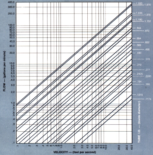 The above chart lists tubing normally available as stock sizes. The bold face sizes are those from which standard BRAZETYTE fittings are fabricated. For special ID's and wall thicknesses consult your tubing supply source. Return To Home Page |